1. Introduction
The present environmental issues are forcing automo-tive manufacturers to cut down vehicle weight in order to minimize fuel consumption and hazardous gas emissions. The main focus is to replace conventional steels with lightweight materials. But, the lightweight materials must be capable of good mechanical and corrosion performance. Presently, aluminum alloys and carbon fiber reinforced plastics (CFRP) are the most attractive candi-dates because of their high strength-to-density ratio. However, as conventional spot welding technologies are not compatible with the joining of dissimilar materials, designers are becoming interested in various mechanical joining technologies. Self-piercing riveting (SPR) has been identified as one of the feasible joining processes for CFRP to aluminum alloy joints [1-3]. SPR is a cold mechanical joining process. In the SPR technology, a punch is used to force a semi-tubular rivet to pierce the top sheet and flare into the bottom sheet under the guid-ance of a suitable die [4]. An SPR process is generally divided into four stages as shown in Fig. 1. A mechanical interlock between the two sheets can be obtained by this process. In recent years, many advantages over traditional joining methods made SPR one of the important joining process for several renowned automotive companies. However, the galvanic corrosion susceptibility of SPR joints is an economic and safety concern for automotive manufacturers. It is well known that a strong galvanic cou-ple can be formed between CFRP and steel rivets if the joint is exposed to a corrosion environment [5-7]. In gen-eral, CFRP is cathodic and performs as a noble material. The steel rivet is anodic and acts as an active material for corrosion. As a consequence of galvanic corrosion, the joint strength can be reduced and joint life-span can be shortened. Joint integrity such as head height, interlock distance, and remaining bottom material thickness are the well-known determining factors of the SPR joint strength [8]. The head height has been proven to play a crucial role in the quality of CFRP to aluminum alloy SPR joints. Head height can be defined as either proud head height or flush head height. If a rivet head protrudes out of the top CFRPlaminate, proud head height is formed. In con-trast, when the rivet head has deeper indentation as the rivet head penetrates into the top CFRP, flush head height is generated. A flush rivet head can locally damage the top CFRP laminate around the rivet head. The fiber break-age and delamination can reduce the lap shear and fatigue strength of the joints [9]. Furthermore, this phenomena may change the galvanic potential of locally damaged CFRP, and influence on the corrosion performance. Nevertheless, to the authors’ knowledge, no research has been reported on the corrosion behavior of CFRP to alumi-num alloy SPR joints with consideration of rivet head height. But, it is important to identify a rivet head con-dition that can ensure the good corrosion performance of SPR joints. Accordingly, this study is focused on inves-tigating the influence of rivet head height on the corrosion performance of CFRP to aluminum alloy SPR joints. Joints with two different rivet head heights (proud head and flush head) were fabricated. Salt spray corrosion test was carried out to evaluate the corrosion behavior. Single lap shear tensile tests were performed to evaluate the me-chanical performance degradation. In addition, electro-chemical corrosion tests were done to analyze the corro-sion mechanisms.
Fig. 1 Schematic diagram of four stages of SPR process.
2. Experimental Methods
2.1 Specimen preparation
The joint consisted of a thermosetting carbon fiber lami-nate, an aluminum alloy sheet, and a boron steel self-pierc-ing rivet. Almac® (50 – 65% Sn, 20 – 30% Zn, 6 – 11% Al) coating of 18 μm average thickness was applied on the rivet as the corrosion protective sacrificial layer. The mechanical properties of CFRP, aluminum alloys and rivet material used in this study are given in Table 1. The self-piercing rivets of 5.3 mm shank diameter, 7.8 mm head diameter and 6.0 mm length were used for preparing the specimen. The CFRP laminate was fabricated by 7 unidirectional carbon fiber prepreg in the form of 0º and 90º orientation. Fig. 2 shows the cross-section of CFRP laminate and the schematic of prepreg orientation.
Fig. 2 CFRP laminate (a) cross-section, and (b) schematic of unidirectional prepreg orientation.
Table 1 Properties of the materials applied for SPR specimen preparation
Two different aluminum alloys (Al5052-H32 and Al5083-O) were used as a bottom sheet to prepare speci-men with different rivet head heights by the application of same setting force. The specimens were fabricated by an electro-hydraulic riveting system of Bollhoff/RIVSET Gen2. The specimens were prepared according to KSCISO 14273 standard, and had a total length of 230 mm and an overlap of 46 mm. The width of the specimen was 60 mm. A rivet was inserted at the center of the over-lap area. The schematic of single lap shear specimen ge-ometry is shown in Fig. 3. The joining process was per-formed by 4 kN of pre-clamping force and 49 kN of set-ting force.
Fig. 3 Schematic of lap shear SPR joint geometry.
2.2 Salt spray test
The lap joint specimens were placed to a salt spray environment condition (5% NaCl solutions, 7.0 pH of the solution, and temperature 35oC) according to KS D 9502:2009 standard. Four specimens were periodically taken at the aging time of 10, 20, 40 and 60 days. They were cleaned by distilled water and dried by compressed air, and preserved in sealed plastic storage bags to ensure no further corrosion during storage
2.3 Single lap shear test and cross-section
Single lap shear tensile tests were performed to evaluate the mechanical performance of the joints in different salt spray test corrosion time. The tests were done by a cross-head rate of 3 mm/min at the room temperature by a KSTM universal testing machine according to KS B 0802:2003 standard. After tensile shear tests, the mac-ro-fractographic studies were done by using a stereoscope of LEICA EZ4HD to analyze the failure modes. The mi-croscopic analysis of joints was done by sectioning along the centerline of the rivet parallel to the loading direction. Sectioned specimens were mounted in unsaturated poly-ester resin. Then the cross-section of the specimens was metallographically polished and analyzed by an Olympus BX51M microscope. The results are expressed as an aver-age of three measured specimens.
2.4 Electrochemical corrosion test
The components of the joints were electrochemically investigated by open circuit potential (OCP) and potentio-dynamic polarization (PDP) tests. Before the PDP tests, the OCP of two hours were conducted to allow the system (corrosion cell) to reach a steady state. The OCP and PDP of working materials (CFRP, Al5052-H32, Al5083-O, and rivet) were done by using a three-electrode cell config-uration and a VersaSTAT 3 potentiostat. A saturated KCl Ag/AgCl electrode was used as a reference electrode, while a platinum mesh was used as a counter electrode. The working materials were cleaned with distilled water, then ultrasonically cleaned in acetone, and finally rinsed with ethanol and dried with compressed air prior to testing. The tests were carried out at room temperature in 3.5% NaCl solution, prepared by reagent grade NaCl into distilled water. The exposed area of working electrode (CFRP, Al5052-H32, and Al5083-O) to electrolyte was 1.0 cm2, and the exposed area of rivet was the rivet head top surface that is about 0.5 cm2. The PDP tests of alumi-num alloys and rivet were investigated as a potential range of -2.0 V/Ag/AgCl to 1.0 V/Ag/AgCl vs. current density (Icorr). The CFRP was measured as a potential range of -1.0 V/Ag/AgCl to 1.5 V/Ag/AgCl vs. current density (Icorr). The tests were scanned to a maximum current den-sity of 5mA/cm2 at a rate of 0.167 mV/s following by ASTM G5-14 standard. The results are presented as an average value of three repeated experiments.
3. Results and Discussion
3.1 Preparation of proud and flush head height of SPR joint
Different aluminum alloys were used as a bottom sheet to prepare the specimens with different joint integrity, and particularly to achieve different head height by the application of same setting force. Otherwise, the applica-tion of different setting forces is required to produce a different head height. But, the application of different set-ting forces can change the rivet head coating morpholo-gies in a different manner, which may introduce another factor to corrosion performance. The coating morpholo-gies of rivet head before and after the joining process are shown in Fig. 4. The coating thickness on rivet head was measured 18 μm before the joining process, and about 7 μm after the joining process. The coating thickness was reduced by about 61% of its initial thickness. In addition, the coating accumulation was observed at the edge of the rivet head. This phenomenon may happen as a result of coating squeezing out from the contact area between rivet head and rivet punch. At the edge of the rivet head, the coating thickness was increased up to 28%, and it was measured 23 μm. This result is compatible with an earlier research that investigated the effect of joining process on rivet coating morphology. The research reported coating accumulation around the top sheet from rivet shank [10]. Therefore, the change of rivet head coating morphologies in different degree by the application of various setting forces should be avoided for this study. Fig.5 presents the coating thickness on the proud head (CFRP/Al 5083-O joints) and the flush head (CFRP/Al5052-H32 joints) after the SPR joining process by the application of same setting force. The average coating thicknesses on the rivet heads were measured 7.28 μm and 7.09 μm for proud head and flush head, respectively. This 2.6% difference in coating thickness may not have a significant effect on corrosion behaviour. Hence, Al5052-H32 (H32: strain-hardened and stabilized) and Al5083-O (O: annealed) were set as bottom sheet. In spite of, the application of same rivet, die geome-try and setting force; different joint integrity were ach-ieved due to the difference in strength and hardness of Al5052-H32 and Al5083-O. The joint integrity in terms of head height, interlock distance, and remaining bottom material thickness are given in Table 2. In CFRP/Al5083-O,as the rivet head was protruded out of the top surface of the top CFRP sheet, a proud head height was created. In CFRP/Al5052-H32, rivet head penetrated into CFRP laminate because of deeper indentation, and a flush head height was produced. The lower strength and hardness of Al5052-H32 facilitated the higher indentation of the rivet, and produced larger interlock distance of 0.55 mm. But, the deeper indentation of rivet head led to higher head flushness of – 0.10 mm and lower remaining bottom mate-rial thickness of 0.17 mm. On the other hand, the higher strength and hardness of Al5083-O led to the proud head height of 0.28 mm, lower interlock distance of 0.36 mm and higher remaining bottom material thickness of 0.44 mm. Fig. 6 presents the head heights formed by CFRP/ Al5083-O and CFRP/Al5052-H32 SPR joints. In addition, these two aluminum alloys were selected because of their similar corrosion properties. The electrochemical corro-sion test results of Al5083-O and Al5052-H32 are pre-sented in section 3.4.
Fig. 4 Cross-sections of rivet (a) as received condition, and (b) after joining process of CFRP to Al joint, (c) and (d) magnified view of rivet head coating as received condition and after joining process, respectively.
Table 2 Joint integrity produced by CFRP/Al5083-O and CFRP/Al5052-H32 SPR joints
Fig. 5 Coating thickness on rivet head after SPR joining process of (a) proud head height (b) flush head height.
Fig. 6 Cross-sections schematic of CFRP to Al alloy SPR joints with (a) proud head, and (b) flush head, (c) and (d) magnified view of proud head and flush head joints, respectively.
3.2 Salt spray test results of SPR joints
The single lap shear samples were placed in a salt spray corrosion test. Samples were taken after 10, 20, 40 and 60 days of corrosion test. The rivet head corrosion in dif-ferent aging time by salt spray test are presented in Fig. 7. The proud head resisted the formation of red corrosion product for more than 40 days. In contrast, the flush head formed red corrosion product by less than 20 days and experienced severe corrosion on the following aging days. The energy-dispersive X-ray spectroscopy analysis was done to characterize the white and the red corrosion prod-ucts (Fig. 8). Zinc oxide was identified as white corrosion product as a result of rivet coating corrosion, and iron oxide was identified as red corrosion product because of rivet base metal corrosion.
Fig. 7 Corrosion morphologies of rivet head for different salt spray test time of (a) proud head height, and (b) flush head height.
Fig. 8 Energy-dispersive X-ray analysis (EDXA) analysis for white and red corrosion product characterization on rivet head.
3.3 Single lap shear load and failure mode
The single lap shear test of corroded samples at the different aging time was conducted. Fig. 9 indicates the change in peak load at the different aging time of salt spray test. The results showed that the severe rivet head corrosion of flush head led to a reduction of peak load up to 19.5% by 60 days. Moreover, the initial failure mode of rivet pullout from the top and the bottom sheet was changed to rivet pullout from only the top sheet by 40 days of corrosion. In comparison, proud head experienced a reduction of peak load by only 4.7% without any sig-nificant change in failure mode. Fig. 10 shows the initial failure mode and 60 days aged failure mode for proud head and flush head SPR joints.
Fig. 9 Shear load for proud head and flush head SPR joints in different aged salt spray test time.
Fig. 10 Failure mode at initial condition and 60 days aged corrosion of (a) proud head height, and (b) flush head height.
The cross-sections of rivet head at the different aging time of corrosion test were also analyzed (Fig. 11). In case of proud head, the coating of the rivet head was grad-ually corroded with aging time, and no coating was ob-served at 60 days. The result is consistent with the ob-servation of red corrosion product on the rivet head at 60 days (Fig. 7). In comparison, the faster corrosion of rivet head coating was evident for the flush head. The coating was corroded by less than 20 days and exposed the rivet base metal. The red corrosion product was formed due to the rivet material (boron steel) corrosion by 20 days, and eventually, led to severe corrosion of rivet head material by 60 days.
Fig. 11 Cross-section of rivet head at initial condition, and corrosion in 20, 40 and 60 days of salt spray test of (a) proud head height, and (b) flush head height.
The higher indentation of the flush head can locally damage the top CFRP laminate around the rivet head. Unlikely, the proud head did not experience any sig-nificant fiber damages. Fig. 12 shows the fiber damages phenomena of CFRP around the rivet head due to deeper penetration of the flush head. The carbon fiber breakage, delamination, and de-bonding from matrix around the rivet head have been evident in the case of the flush head which is consistent with the findings of a prior study [9].
Fig. 12 CFRP breakage and delamination around the rivet head by flush head SPR joint.
3.4 Electrochemical corrosion analysis
Two different aluminum alloys were applied as bottom sheet to prepare the different head height by the applica-tion of same rivet setting force. The potentiodynamic po-larization test results of Al5083-O and Al5052-H32 are shown in Fig. 13. The corrosion potential of Al5083-O bottom sheet, the difference in the potential value of 0.07 V may not have a significant influence on the rivet head corrosion mechanism which is the point of interest in this study.
Fig. 13 Potentiodynamic polarization curve of Al5083-O and Al5052-H32 aluminum alloys.
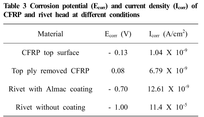
In proud head height, a galvanic coupling was in be-tween rivet head and CFRP top surface. But, in flush head height, a galvanic coupling was formed between rivet head and damaged CFRP. In this situation, the corrosion poten-tial measurement of damaged CFRP is essential. But, it is very challenging to measure the corrosion potential of damaged CFRP around the rivet head. In order to generate a similar condition of fiber breakage and delamination, the top ply of the CFRP laminate was peeled off. The fiber breakage and delamination from the matrix happened during the removal of top ply. Fig. 14 shows the morphol-ogy of damaged fiber after peeling off the top ply of the CFRP sheet. The potentiodynamic polarization tests were conducted for the top surface of CFRP laminate as re-ceived condition and the surface with damaged fibers after removal of the top ply. Fig. 15 presents the potentiody-namic polarization test results of CFRP. The corrosion po-tential of CFRP laminate was measured as – 0.13 V. In contrast, 0.08 V was measured for damaged fibers. The results are compatible with previous research which re-ported that the different surface condition of CFRP lami-nate produced by polished and unpolished specimen per-formed different corrosion behavior [11]. The potentiody-namic polarization tests were conducted for rivet head with coating and after removal of coating (Fig. 16). The corrosion potential and corrosion current density of CFRP and rivet are presented in Table 3. Here, the galvanic cou-pling of CFRP to rivet head is 0.21 V higher for the flush head than that of the proud head at the initial time of corrosion test. As a result, the corrosion of the rivet coat-ing was faster for the flush head. After rivet head coating corrosion, the base metal of rivet was exposed to the cor-rosive environment, and the red corrosion product was formed by only 20 days for the flush head. At this mo-ment, the galvanic coupling was formed in between CFRP damaged fiber and rivet base metal boron steel. The corro-sion mechanism of proud head and flush head are pre-sented as a schematic in Fig. 17. The corrosion potential of rivet without coating was measured as – 1.0 V, which was 0.3 V more anodic than that of the rivet with coating. The higher amount of Sn in Almac® coating may lead to lower anodic potential of coated rivet than that of an uncoated rivet. At this situation, strong galvanic coupling of 1.08 V was formed in between damaged CFRP and rivet head (boron steel). The increase in the potential of galvanic coupling became a further acceleration factor to corrosion after the loss of rivet head coating by 20 days. Henceforth, the rivet head of flush head was severely cor-roded by 60 days. Comparatively, the corrosion of a proud head was not as bad as a flush head. At the starting of the corrosion test, 0.57 V potential difference of CFRP laminate and rivet head led to the slower corrosion of rivet head coating. At 60 days of aging time, the loss of coating led to the formation of red corrosion product on rivet head. In addition, the loss of rivet head coating can increase the galvanic coupling up to 0.87 V which is not as severe as 1.08 V of a flush head case.
Fig. 14 Fiber breakage and delamination by removal of CFRP top ply.
Fig. 15 Potentiodynamic polarization curve of CFRP (top surface of received condition and after removal of top ply).
Fig. 16 Potentiodynamic polarization curve of rivet head (with Almac® coating and after removal of coating.
Fig. 17 Schematic diagram of corrosion mechanism of rivet head at different aging time for (a) proud head height, and (b) flush head height.
Table 3 Corrosion potential (Ecorr) and current density (Icorr) of CFRP and rivet head at different conditions
 4. Conclusions
The research has evaluated the corrosion performance of a proud head and a flush head condition of CFRP to aluminum alloy SPR joints. In the flush head, the top CFRP sheet was locally damaged due to the higher pene-tration of the rivet head. The corrosion potential of dam-aged CFRP was measured higher than the corrosion poten-tial of CFRP at the received condition. The increased po-tential of damaged CFRP accelerated the corrosion of sac-rificial coating on rivet head. The faster corrosion of rivet head coating exposed the rivet base metal (boron steel). Consequently, a strong galvanic coupling was formed be-tween damaged CFRP and rivet head base metal. This phenomena further accelerated rivet head corrosion. As a result of severe rivet head corrosion, the joints with flush head experienced 19.5% of shear load reduction by 60 days of salt spray test. Moreover, a change in failure mode was happened for flush head joints due to intense corro-sion of the rivet head. In the proud head, the corrosion of rivet head is not as drastic as flush head due to the comparatively weaker galvanic coupling of CFRP top sur-face and rivet head. Thus, the rivet base material corrosion was resisted for more than 40 days of salt spray test. The joints with proud head experienced only 4.7% of shear load reduction by 60 days of salt spray test. In addition, no significant change in failure mode was observed. Therefore, the rivet head height needs to be optimized to restrict CFRP damages. The head flushness must be avoided or reduced to enhance the corrosion performance of the joints.
참고문헌
- J. Kang, H. Rao, R. Zhang, K. Avery, and X. Su, Mater. Sci. and Engi., 137, 12025 (2016).
- J. Zhang and S. Yang, J. Compos. Mater., 49, 1493 (2014). https://doi.org/10.1177/0021998314535456
- A. Pramanik, A. K. Basak, Y. Dong, P. K. Sarker, M. S. Uddin, G. Littlefair, A. R. Dixit, and S. Chattopadhyaya, Compos. Part A, 101, 1 (2017). https://doi.org/10.1016/j.compositesa.2017.06.007
- L. Calabrese, E. Proverbio, E. Pollicino, G. Galtieri, and C. Borsellino, Corros. Eng. Sci. Techn., 50, 10 (2015). https://doi.org/10.1179/1743278214Y.0000000168
- S. U. Ofoegbu, M. G. S. Ferreira, and M. L. Zheludkevich, Materials, 12, 651 (2019). https://doi.org/10.3390/ma12040651
- M. Mandel and L. Kruger, Mater. Today Proc., 2, 131 (2015). https://doi.org/10.1016/j.matpr.2015.05.030
- M. Mandel and L. Kruger, Corros. Sci., 73, 172 (2013). https://doi.org/10.1016/j.corsci.2013.03.033
- D. Li, A. Chrysanthou, I. Patel, and G. Williams, Int. J. Adv. Manuf. Tech., 92, 1777 (2017). https://doi.org/10.1007/s00170-017-0156-x
- H. M. Rao, J. Kang, G. Huff, K. Avery, and X. Su, SAE Int. J. Mater. Manuf., 10, 167 (2017). https://doi.org/10.4271/2017-01-0477
- M. Esfahani, Y. Durandet, J. Wang, and Y. Wong, Adv. Mater. Res., 448-489, 1501 (2012).
- X. Wu, J. Sun, J. Wang, Y. Jiang, and J. Li, Mater. Corros., 70, 1036 (2018).