1. Introduction
A district heating system is an urban infrastructure that collectively supplies heating water, which is economically produced by large-scale heat production facilities, such as a combined heat & power (CHP) plant and peak load boiler (PLB) power plant [1-3]. Many different types of heat exchangers are used for these district heating systems. The heat exchanger in a district heating system not only acts to provide heat transfer but also serves to prevent mixing between the thermal fluids. Therefore, damage to the heat exchanger causes various problems such as a de-crease in the heat exchange efficiency and the con-tamination of a thermal fluid. As a result, the importance of maintaining and managing heat exchange facilities has become an issue in order to improve energy production, transportation, storage efficiency and to ensure overall heating quality.
Among various types of heat exchangers, the shell and tube heat exchanger is the most widely used, not only district heating systems, but also various industries such as refineries, petrochemical plants, steelworks and the like. Generally, the shell and tube of heat exchanger are de-signed with dissimilar materials, which causes various failure cases like mechanical failure, galvanic corrosion and stress corrosion cracking (SCC) [4-6]. In particular, austenitic stainless steel, which is weak against SCC, is mainly used for the tube, SCC can occur in a high temper-ature environment containing even a small amount of chloride ions [6-8].
The objective of this paper is the failure analysis of a heat exchanger tube in a district heating system. This failure analysis of heat exchanger tubes was conducted by using visual inspection, optical microscopy (OM) and scanning electron microscopy (SEM) with energy dis-persive spectroscopy (EDS).
2. Experimental procedures
2.1. Background information
The heat exchanger has been in operation for 18 years. The materials of tube and shell were made of SS304 and A516 gr 60, respectively. Table 1 lists chemical composi-tions of materials. The outside and inside of the tube con-sist of steam and district water. The temperature and pres-sure of steam was 153 °C, 0.1 MPa. The inlet and outlet district heating water temperatures were, 62 °Cand 98 °C, respectively, and both were at a pressure 0.5 MPa.
Table 1 Chemical composition of the failed heat exchanger tube and shell (wt%)
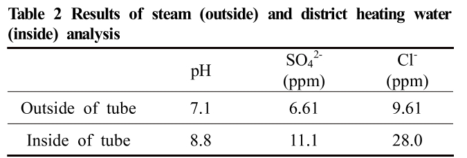
The chemical element analysis of steam and district heating water is listed in Table2. The tube thickness and outer diameter were 1.4 mm and 19 mm, respectively. This heat exchanger had numerous standby conditions. During this period, the temperature was usually lowered to room temperature, without any special measures. Since the materials of shell and tube are dissimilar, thermal stress occurs in the tube due to the difference in the ther-mal expansion coefficient. Consequently, tensile and com-pressive stresses act on the tube due to the repetition of the operation and standstill of the heat exchanger.
Table 2 Results of steam (outside) and district heating water (inside) analysis
 2.2. Characterization methods
A visual inspection of failed tubes was conducted both inside and outside of the fracture zones, in order to inves-tigate the shape, size, causes of failure. OM was used to observe crack morphologies in the failed tube. For opti-cal analysis, the tubes were mounted, polished to 1 μm using diamond suspension and etched in a Vilella's reagent (15 mL HNO3+ 30 mL HCl + 45 mL glycerol) for 30s. EDS was used to analyze the chemical elements of corro-sion products deposited on the cracks, and fractrography of the ruptured surface was observed using SEM.
3. Results and discussion
3.1. Visual inspection
The failure tubes are shown in Fig. 1 and Fig. 2. Failure of the tube occurred in the whole area of the tubes, and the cracks were formed both the circumferential and longi-tudinal directions. Cracks appeared not only at the end of the tube connected to the shell but also throughout the tube. The size of the cracks varied from micron scale to complete rupture. Cracks were mostly formed in the cir-cumferential direction, and a few cracks did occur in the longitudinal direction (Figs. 1a and 1b). The fractured sur-faces were almost matched with each other, and plastic deformation could not observe. Brown oxide and orange oxide were observed on the outside and inside of the tube, respectively (Figs. 2a and 2b). Many pits were found ad-jacent to the cracks formed on the tube surface (Fig. 2c). These pits could act as a crack initiation point due to the stress concentration, pitting corrosion could cause tube failure.
Fig. 1 Photographs of the failed tubes; (a) circumferential and longitudinal direction crack, and (b) circumferential direction crack.
Fig. 2 Corrosion products formed on the tube surface; (a) outside of the tube, (b) inside of the tube, and (c) pits adjacent the crack.
3.2. Microscopic examination
The cross sections of the failed tubes are shown in Fig. 3. Pits were found on both sides of the tubes. Pits at the outer side of the tube were deeper than those at the inner side. Most of the cracks started from the outside of the tube. At the crack initiation site, the pits were observed, which verifies that pits acted as initiating points of the cracks. In Fig. 4, the numerous cracks had transgranular branched shape and sharp tip which are typical forms of SCC [7].
Fig. 3 Cross-sectional views of the failed tubes.
Fig. 4 Microstructure of the outer side of the failed tube wall.
3.3. Chemical element analysis of corrosion product
Fig. 5 shows the SEM image and EDS data of the corro-sion product adjacent to the crack on the outer surface of tube. The corrosion products were formed with a max-imum thickness of about 20 μm. The EDS analysis shows not only Fe and O peak but also Cl peak. The enrichment of Cl ion means that cracks were affected by chloride ion. Although the steam and district heating water only contain a small amount of chlorideion, chloride can lo-cally concentrate on the surface of the tube due to the repetition of the operation and standstill period of the heat exchanger [9-13]. This may lead to chloride-induced pit-ting corrosion and cracking.
Fig. 5 (a) Corrosion products formed on the cracks and (b) EDS spectra of the corrosion product.
3.4. Fractography
Fig. 6 shows SEM fractographs of the failed tube. The interior of the crack was divided into two areas with and without corrosion products (Figs. 6a and 6b), and the frac-ture mode possesses both cleavage and quasi-cleavage appearance. Striations are observed on the fracture surface with corrosion products, which is an evidence of corrosion fatigue cracking (CFC) [7,14]. The fracture was caused by corrosion cracking accelerated by fatigue of the tube. Generally, the boundary between SCC and CFC phenom-enon is not clear, but CFC often regarded as a subset of SCC in the same environment [15,16], so they can occur at the same time. When SCC and CFC occur together, SCC propagation rate is faster than that of CFC and there-by SCC has the most significant influence on the life time of the material [7].
Fig. 6 SEM fractographs of the fracture surface; (a) a region without corrosion products, and (b) a region with corrosion products.
3.5. Calculation of thermal stress
Fig. 7 shows the shell-tube heat exchanger. The tube and shell are welded to the tube sheet and the designed tube and shell length is 4,500 mm (at 25 °C). As shown in Table 1, the tube and shell are made of SS304 and A516 gr 60 materials. Since the tube and shell having different materials are fixed to the tube sheet, thermal stress is generated in the tube and shell according to the temperature change. In accordance with the onset of de-formation, the stress applied to the tube is calculated by the following equations, and the information related to thermal stress calculation is listed in Table 3.
Fig. 7 Schematic diagram of the shell-tube heat exchanger.
Table 3 Calculation of thermal stress on tube and shell
(1)
(2)
(3)
where Δl is the length increased by temperature change, l0 is the initial length, αis thermal expansion coefficient, T0 is initial temperature, ε is the strain due to the differ-ence in thermal expansion coefficient, ΔL is the difference in length of shell and tube due to temperature change, L0 is the length of the shell or the tube at a given temper-ature, σ is the thermal stress and E is the Young’s modulus. If the length of the shell is longer than the tube, tensile stress is generated to the tube. As a result, a tensile stress of 46.9 MPa and a compression stress of 127.9 MPa are generated in the tube during the operation period and the standstill period of the heat exchanger, respectively. Although the stress generated in the tube is a small value to be failed, but it is sufficient to induce SCC. SCC can occur with relatively low stress (~98 MPa) for the SS304 [17].
3.6. Failure mechanism
When the operation and standstill periods of the heat exchanger are repeated, the district heating water in the tube always flows, but the wet and dry environments are repeated on the outside of the tube. When the temperature decreases, the water vapour containing chloride ion con-denses in the form of water droplets or water film on the surface of the tube. When the temperature rises, the water droplets and water film evaporate and the chloride ion concentration increases [11-13]. In such an environ-ment in which wet and dry are repeated, a very high con-centration of chloride can be easily generated locally [9,10]. Consequently, although the concentration of chlor-ide contained in the steam is low, chloride condensation will occur on the outside of the tube surface by repeating the operation and standstill period of the heat exchanger. Thereafter, pitting corrosion occurs on the surface of the tube where chloride is locally concentrated. The formed pit repeatedly undergoes thermal stress and finally cracks initiate from the pit. The failure of the heat exchanger tubes occurred due to the combined effect of pitting and stress.
4. Conclusions
In this study, a PLB heat exchanger tube failure was investigated using visual inspection, microscopic exami-nation, EDS analysis and SEM fractography. According to the above investigation, the causes of damage to the heat exchanger tube were inferred as follows:
1. The cracks which occurred in the circumferential direc-tion in the heat exchanger tube were affected by the thermal stress generated by the difference in the materi-al of the tube and the shell.
2. The cyclic operation and the standstill period resulted in the local enrichment of chloride ions on the tube surface. As a result, pitting corrosion was generated on the chloride-enriched surface, and cracks were ini-tiated from the pits on the outer surface of tube by thermal stress.
3. The cracks showed transgranular, branched propagation and sharp edge, and the fracture surface had the form of a brittle fracture without corrosion product. This is a typical form of stress corrosion cracking.
4. The failure of the tube occurred due to chloride induced SCC in the presence of thermal stress and pitting.
References
- B. Atli, B. Benny, and F. R. Hans, Energ. Convers. Manage., 36, 297 (1995). https://doi.org/10.1016/0196-8904(95)98895-T
- H. Lund, B. Moller, B. V. Mathiesen, and A. Dyrelund, Energy, 35, 1381 (2010). https://doi.org/10.1016/j.energy.2009.11.023
- M. K. Hong, J. M. Cho, M. J. Song, W. C. Kim, T. B. Ha, and S. Y. Lee, Corros. Sci. Tech., 17, 287 (2018).
- R. T. Mousavian, E. Hajjari, D. Ghasemi, M. K. Manesh, and K. Ranjbar, Eng. Fail. Anal., 18, 202 (2011). https://doi.org/10.1016/j.engfailanal.2010.08.022
- S. Rongjuan, W. Weiqiang, L. Yan, L. Dong, and L. Wei, Eng. Fail. Anal., 45, 398 (2014). https://doi.org/10.1016/j.engfailanal.2014.07.013
- X. Shugen, W. Chang, and W. Weiqiang, Eng. Fail. Anal., 51, 1 (2015). https://doi.org/10.1016/j.engfailanal.2015.02.005
- D. A Jones, Principle and Prevention of Corrosion, 2nd ed., p. 238, pp. 257 - 259, Prentice Hall, NJ (1997).
- M. Borchert, G. Mori, M. Bischof, and A. Tomandl, Corros. Sci. Tech., 14, 280 (2015). https://doi.org/10.14773/cst.2015.14.6.280
- Philip A. Schweitzer, Fundamentals of Metallic Corrosion; Atmospheric and Media Corrosion of Metals, 2nd ed., p.113, CRC Press (2007).
- J. R. Davis, Corrosion: Understanding the Basis, 1st ed., p. 314, ASM International (2000).
- B. Maier and G. S. Frankel, J. Electrochem. Soc., 157, 302 (2010).
- R. Parrott and H. Pitts, Chloride stress corrosion cracking in austenitic stainless steel, http://www.hse.gov.uk/research/rrpdf/rr902.pdf (2011).
- Y, Tsutsumi and A. Nishikata, Corros. Sci., 49, 1394 (2007). https://doi.org/10.1016/j.corsci.2006.08.016
- R. K. Singh Raman, S. Jafari, and S. E. Harandi, Eng. Fract. Mech., 137, 97 (2005). https://doi.org/10.1016/j.engfracmech.2014.08.009
- R. H. Jones, Stress-Corrosion Cracking Materials Performance and Evaluation, 2nd ed., p. 1, ASM International, USA (2017).
- A. Visser, G. Mori, M. Panzenbock, and R. Pippan, Corros. Sci. Tech., 14, 172 (2015). https://doi.org/10.14773/cst.2015.14.4.172
- G. Cragnolino and D. D. Macdonald, Corrosion, 38, 406 (1982). https://doi.org/10.5006/1.3577354