1. Introduction
Shipping contributes to air pollution by the burning of fossil fuel. The emitted NOx(nitrous oxides) and SOx(sulfur oxides) together with particulate compounds such as soot contribute to the anthropogenic perturbation of the Earth’s radiation budget [1]. The emission of NOx and SOx has different consequences for the atmosphere. Especially, SO2(sulfur dioxide) is oxidized to SO3(sulfur trioxide) and eventually forms sulfuric acid, which con-tributes to acid rain and provides cloud condensation nu-clei by the formation of secondary particles, thereby in-creasing the albedo. Owing to the reactivity of sulfur gases in the atmosphere, most anthropogenic SO2 emissions are deposited locally, therefore shipping contributes to coastal air pollution [2]. According to the IMO Annex VI of MARPOL 73/78, Regulations for the Prevention of Air Pollution from Ships, which has been ratified and effec-tively entered into force from May 2005, the SOx emis-sions are regulated by setting a maximum limiting value on the fuel sulfur content of 4.5% w/w, and the SOx limit applies to all vessels [3]. Recently, the 2020 deadline was confirmed at the 70th session of IMO’s MEPC (Marine Environment Protection Committee) held in October 2016. The IMO will enforce a new 0.5% global sulfur cap on fuel content from 1 January 2020, lowering from the pres-ent 3.5% limit. Thus, the switch to burning either MGO (Marine Gas Oil) or ULSFO (Ultra Low Sulphur Fuel Oil) is an option for ship owners to be in compliant with the IMO regulation [4]. However, fuel cost represents one of the heaviest voices in ship’s budget, and switching from HFO (Heavy Fuel Oil, 3.5 - 4.5% S w/w) to MDO (1.0% S w/w) or MGO (0.1% S w/w) would imply a significant increase of costs. Thus, seawater SO2 scrubbing, which is especially spray scrubbing, is a promising alternative to comply with the IMO regulation [5]. Fig. 1 illustrates schematic diagram of seawater spray scrubber for ship’s engine. The advantages of using seawater scrubber involve simple plant design, no addition of chemicals and solid by-products. On the other hand, there is a problem that the acidified effluent could accelerate corrosion of the in-ternal seawater pipe. The SO2 and SO3 in the exhaust gas from ship’s engine dissolve and occurs whereby the SO2 is ionized to bi-sulfite and sulfite, which is then readily oxidized to sulfate in seawater containing oxygen. The ionization of SO2 and the H2SO4(sulfuric acid) formed from SO3 (sulfur trioxide) also produces acidity [6]. Therefore, the corrosion problems in the scrubber seawater piping system have occurred severely.
Fig. 1 Schematic diagram of seawater spray scrubber for ship’s engine [7].
Fig. 2 illustrates heavily corroded interior of pipes for seawater scrubber system. According to Marine Log [8], underwater repair specialist has been carrying out an in-creasing number of repairs to the pipework and overboard outlets of ships equipped with exhaust gas scrubbers. This is because although scrubber systems remove harmful SOx compounds from the exhaust gases of marine diesel en-gines burning high-sulfur heavy fuel oils, the resulting res-idue removed from these gases could have considerably and highly corrosive effects on the scrubbers’ internal pi-pework and outlet.
Fig. 2 Heavily corroded scrubber pipe.
Many researchers have studied corrosion characteristic of metals in diluted or concentrated sulfuric acid. ZekariasE.Gebreyes et al. [9] investigated the corrosion rate of low carbon steel, especially sheet metals in the acidic solution for 5 days, and the weight loss measurement was taken with the interval of 24 hours. This research revealed that the corrosion of low carbon steel in the acidic solution was augmented, and calculated value showed that the cor-rosion rate increased with increase in time and molar con-centration of the acids. MGR Mahlobo et al.[10] eval-uated the influence of SO2 on the corrosion carbon steel under different SO2 concentrations (0.5, 1.0, and 5%) in combination with subcritical CO2. The weight loss results showed that corrosion rate increased with SO2 concen-tration with corrosion rate up to 7.45 mm/year while at 0% SO2 the corrosion rate was 0.067 mm/year. Ekhlas A. Salman Al-zubidy et al.[11] studied the corrosion be-havior of copper and carbon steel in 1 M concentration of HCl (hydrochloric acid) and H2SO4. In this case, the corrosion rates of carbon steel in the acidic media found to be higher.
Furthermore, Mohd Asyadi Azam et al. [12] figured out that the influence of H2SO4 concentration to corrosion behavior of the internal surface of the pipeline by using Tafel extrapolation method. As a result, the corrosion rate increased with higher concentration of sulfuric acid. The microscopic analysis also confirmed the presence of pit-ting corrosion, and micrometer thick of corrosion product was developed on the internal surfaces of the pipe. Y.Kobayashi et al.[13] described corrosion fatigue for notched specimens in diluted sulfuric acids. Life of ship structural steel in diluted sulfuric acids was shorter than that in seawater. This is exactly because there are severe dissolutions of iron in diluted sulfuric acids. These facts mean that carbon steel in acidified seawater is more sus-ceptible to corroded than in natural seawater. In order to protect the pipe against further corrosion in the acidic en-vironment, steel pipes are with polyethylene, rubber lin-ing, galvanized piping or GRE (Glass Reinforced Epoxy) pipe [14]. However, due to many potential risks such as abrasion, adhesion failure, and blistering, coating failures are highly likely to occur [15], resulting in the corrosion problem. Thus, corrosion damage of seawater piping sys-tem for scrubber would occur repeatedly and frequently unless we offer fundamental corrosion control method. In this study, electrochemical measurement and weight loss of carbon steel, which is used as seawater pipe in most ships, in different diluted sulfuric acid solutions were performed to determine corrosion rate, corrosion current density, corrosion potential, electrochemical behavior, and impressed-current density. It is hoped that the results from this study will suggest fundamental data to deal with cor-rosion problem in scrubber seawater piping system.
2. Experimental Methods
2.1 Materials
The specimen used for this study was carbon steel (KS D 3507) which is typically used as the seawater piping system. The chemical compositions of specimen are shown in Table 1. The carbon steel sheet of 1 mm thick-ness was cut into 100 mm ×20 mm coupons (Area = 6.57 in2).
Table 1 Chemical compositions of specimen
G. Caiazzo et al.[5] experimented SO2 adsorption test by using seawater spray tower scrubber. In his study, SO2 inlet concentration in the range 500 - 1000 ppm were used, corresponding to typical concentrations obtained from die-sel engine exhaust gas when burning HFO (sulfur content in the range 2.5 - 4.5% w/w). Test exhaust gas was de-sulfurized, and concentration of sulfates in seawater after the test was in the range of 0.02 - 0.03 M. Based on this research data, therefore, different diluted sulfuric acid solutions based on the seawater (0, 0.01, 0.02, and 0.03 M) were prepared by using sulfuric acid (Product Code: S1423, SAMCHUN CHEMICALS)
2.2 Methods
2.2.1 Electrochemical measurement
The electrochemical measurements used to study the corrosion behavior are a measurement of open-circuit po-tential, polarization resistance, potentiodynamic and po-tentiostatic polarization.
First, the variation of the open-circuit potential of speci-men as a function of time was measured for 10000 sec-onds, and the open-circuit potentials were measured by using SSCE (Silver-Silver/Chloride Electrode).
Secondly, to calculate corrosion rate, corrosion current density, and corrosion potential by electrochemical polar-ization method, we utilized potentiodynamic curves and polarization resistance tests. The potentiodynamic curves were obtained by scanning the potential range from catho-dic potential of –100 mV to anodic potential of +100 mV vs SSCE with respect to the open-circuit potential at a scan rate of 0.167 mV/S. Equilibrium time leading to the steady state of specimen was 1 hour. The polarization re-sistance tests were obtained by scanning the potential range in ±20 mV vs SSCE with respect to the open-circuit potential at a scan rate of 0.167 mV/S, and then calculated. Lastly, the potentiostatic polarization was carried out for 600 seconds, and initial delay time leading to the steady state of specimen was 300 seconds. Jeong et al. [16] sug-gested that the cathodic protection potential from ̶1,300 to –1,200 mV vs SSCE should be maintained because in this range the concentration polarization by oxygen reduc-tion appeared, and then he could prevent carbon steel from corrosion and hydrogen embrittlement caused by hydrogen evolution. On the basis of suggestion from Jeong’s re-search, we determined the cathodic protection potential at –1,100 mV vs SSCE. This is because the cathodic pro-tection potential we set not only appeared the concen-tration polarization by oxygen reduction but also avoided occurring hydrogen embrittlement caused by hydrogen evolution.
The experimental apparatus, which was consisted of water bath containing solution, potentiostat (Gamry refer-ence 600) to perform electrochemical experiment and to measure many parameters. The three-electrode system was employed with reference electrode (Ag/AgCl electrode), counter electrode (platinum), and working electrode (specimen). The schematic diagram of experimental appa-ratus is illustrated in Fig. 3.
Fig. 3 Schematic diagram of experimental apparatus, 1-working electrode (specimen), 2-counter electrode (platinum), 3-Reference electrode (Ag/AgCl electrode), 4-Water bath, 5-Potentiostat (Gamry Reference 600).
2.2.2 Weight loss measurement
Weight loss measurements were conducted under total immersion using beaker containing 2 L test solution. Before weight loss experiment, the specimens were weigh-ed to the 2nd decimal of gram by using digital balance. After that the specimens were immersed and exposed to different diluted sulfuric acid solutions for 30 days. At the end of weight loss experiment, the specimens were washed by tap water with brushing to remove the corro-sion by-product that formed on the surface, washed with distilled water, dried with clean tissue, rinsed in acetone and dried.
The corrosion rate was calculated by the equation (1):
(1)
Where, Corrosion rate (MPY = mils per year: mili-inch penetration per year), Weight loss (mg), Area (in2), and Time (hour)
3. Results and Discussion
3.1 Electrochemical measurement
3.1.1 Open-circuit potential
Fig. 4 shows the OCP (Open-Circuit Potential) curves of carbon steel for 10000 seconds immersion time in di-luted sulfuric acid solutions. In all cases, it was clear that the OCP decreased with time and approached a steady- state after 4000 seconds. Compare to the OCP of specimen in only seawater, the OCP of specimens in various diluted sulfuric acid solutions shifted toward more positive direc-tion with increasing concentration [12]. However, the OCP curves appear that potentials of carbon steel in seawater 0.01, 0.02, and 0.03 M H2SO4 were hardly deviated by increasing diluted sulfuric acid concentration. This is be-cause the intensities of the steady-state anodic and catho-dic processes are changed to roughly the same degree [17]. Furthermore, the fact that the OCP curves decrease con-tinuously means that continuous dissolution of the carbon steel specimens in low diluted sulfuric acid proceeded, therefore, no passive film from corrosion by-product was observed.
Fig. 4 Open-circuit potential curves as a function of time in different sulfuric acid concentration.
3.1.2 Polarization resistance test
Fig. 5 shows the results of polarization resistance test in different diluted sulfuric acid solutions. To begin with, tendency of corrosion potential was approximately in agree-ment with the results of the OCP in this study; corrosion potential shifted toward more positive direction with an increase of diluted sulfuric acid concentration. Furthermore,not only corrosion current density (icorr) but also corrosion rate increased as diluted sulfuric acid concentration increased. Lastly, Polarization resistance (Rp) decreased with increasing diluted sulfuric acid concentration, and this fact represents that the corrosion resistance of carbon steel was exacerbated with an increase of diluted sulfuric acid concentration. This result is in agreement with Mohd Asyadi Azam et al. [12].
Fig. 5 The results of polarization resistance test in different sulfuric acid concentration (a) Corrosion potential, (b) Corrosion current density, (c) Corrosion rate, (d) Polarization resistance.
3.1.3 Potentiodynamic polarization test
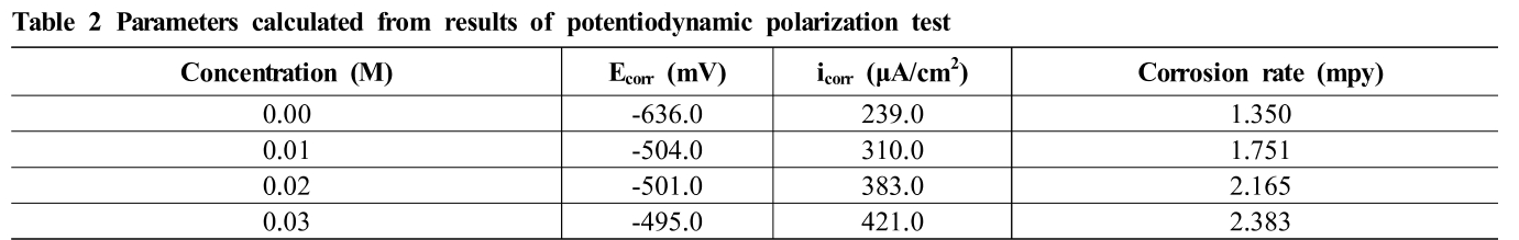
Fig. 6 shows potentiodynamic polarization curves of specimen in diluted sulfuric acid concentration. The ex-periments have been done with four kinds of diluted sulfu-ric acid concentrations at only seawater, seawater 0.01, 0.02, and 0.03 M H2SO4 respectively. As can be seen in potentiodynamic curves, it is clear that the increasing in acid concentration lead to displacement of corrosion po-tential to more positive values. Table 2 gives the values of corrosion potential (Ecorr), corrosion current (icorr), and corrosion rate. The corrosion potential of seawater was –636.0 mV/SSCE, which was –132 mV more negative than that of seawater 0.01 M H2SO4 solution. The dis-placement in corrosion potential to more positive values as increase in diluted sulfuric acid concentration indicates on the contribution of each of the cathodic and anodic process in the process of corrosion, where the increase in Ecorr values shows that the corrosion of carbon steel in diluted sulfuric acid solutions is under the anodic con-trol [18]. The corrosion rate and corrosion current density of the specimens increased as diluted sulfuric acid concen-tration increased. When the solution was diluted into less concentrated, the corrosion current density also decreased proportional to the corrosion rate but inversely propor-tional with corrosion potential. The corrosion current den-sity (icorr) increased from 239.0 μA/cm2 at only seawater to 421.0 μA/cm2at seawater 0.03 M H2SO4. The study of Mohd Asyadi Azam et al.[12] is in agreement with our results.
Fig. 6 The results of potentiodynamic polarization test, (a) Tafel extrapolation curves, (b) Corrosion potential, (c) Corrosion current density, (d) Corrosion rate.
Table 2 Parameters calculated from results of potentiodynamic polarization test
 3.2 Weight loss measurement
Fig.7a shows the weight loss results of specimens. It shows that the weight loss of carbon steel sheet increased with an increase of diluted sulfuric acid concentration. In the natural seawater (i.e. only seawater), weight loss was 130 mg. Furthermore, weight loss in seawater 0.01, 0.02, and 0.03 M H2SO4 was 190, 320, and 910 mg respectively. This observation is attributable to the fact that the rate of chemical reaction increases with increasing concen-tration, leading to increment of weight loss [9]. Although concentrated sulfuric (from 65 to 100%) acid forms a pro-tective iron sulfate film on the carbon steel that prevents carbon steel metal loss [19], carbon steel in diluted sulfu-ric acid solution could not form passive film, resulting in increase of metal weight loss.
Fig. 7 The results of weight loss method, (a) Weight loss of specimens before and after experiment, (b) Corrosion rate in various diluted sulfuric acid concentration.
Fig. 7b shows the corrosion rate of carbon steel in di-luted sulfuric acid calculated by weight loss results. With an increase of concentration, the corrosion rate increased. Significant increase in corrosion rate was observed when diluted sulfuric acid concentration was at seawater 0.03 M H2SO4. Corrosion rate of carbon steel in diluted sulfuric acid increased up to 13.05 mpy, which was 7-fold greater than that of carbon steel in natural seawater (1.86 mpy). Increasing diluted sulfuric acid concentration in the sol-ution leads to an increase in the corrosion rate [17]. Similar tendency of corrosion rate in diluted sulfuric acid were obtained in D.B. PATIL et al. [20] and Sami AbualnounAjeel et al.[21]. The fundamentals behind in-creasing corrosion rate could be elucidated by the for-mation of FeSO3(ferrous sulfate) when SO2 is added in seawater as shown in equations (3) & (4):
SO2 + H2O→ SO32- + 2H+ (3)
Fe2++ SO32-→ FeSO3 (4)
FeSO3 is one of the corrosion products that form on the metal surface when SO2 is added in the water or sea-water thus increasing the corrosion rate considerably [10]. Consequently, a dash of sulfuric acid dissolved into sea-water or water had a strong impact on the corrosion of carbon steel material.
3.3 Potentiostatic polarization test
Fig.8a shows the results of potentiostatic polarization in different diluted sulfuric acid solutions. Cathodic pro-tection potential was set at –1,100 mV/SSCE. As can be seen in potentiostatic polarization curves, it provides an information of the impressed-current density, iapp, for cathodic protection to –1,100 mV/SSCE of cathodic pro-tection potential. In all cases, at the beginning of the test, there was a general tendency for a high impressed-current density, while its current density gradually decreased as time went by. The higher diluted sulfuric acid concen-tration was, the greater impressed-current density for cathodic protection applied. Compare to natural seawater, impressed-current density for cathodic protection in di-luted sulfuric acid solution was tremendously large. The lowest impressed-current density of approximately 7.1 mA/cm2was observed in the natural seawater, and the highest impressed-current density of approximately 92.5 mA/cm2was observed in seawater 0.03 M H2SO4. The difference between the highest and lowest value was al-most 13-fold. Like this, in order to prevent the inner sur-face of seawater pipe, especially used for SOx scrubber from corrosion, a huge impressed-current is necessary. This is why the coatings have been used to reduce current requirement. Even though the coatings usually used to re-duce current requirements for cathodic protection are not resistant to strong acid solutions [19], the coatings for the inner surface of pipe in seawater SOx scrubber would be practical because diluted sulfuric acid in the seawater SOx scrubber is relatively low level of acid solution. In con-clusion, we should consider combining the surface coating with corrosion control technology in the seawater pipe for SOx scrubber.
Fig. 8 The results of potentiostatic polarization test maintaining cathodic protection potential at -1,100 mV/SSCE under various conditions, (a) Potentiostatic polarization curves in different diluted sulfuric acid solutions, (b) Potentiostatic polarization curves in different flow velocities.
Fig.8b demonstrates the results of potentiostatic polar-ization in various flow velocities. Cathodic protection po-tential was also set at –1,100 mV/SSCE. As can be seen in the graphs, the higher flow rates maintained, the greater impressed-current density appeared. In the stagnant sea-water 0.01 M H2SO4, roughly 43.8 mA/cm2of im-pressed-current density was observed. Moreover, the sol-ution was stirred at 20% output (360 RPM) of stirrer, roughly 110.4 mA/cm2of impressed-current density was observed. Lastly, the solution was stirred at 50% output (900 RPM) of stirrer, nearly 126.7 mA/cm2of im-pressed-current density was observed. This is because in-creased flow at the surface could change the limiting cur-rent density, leading to that the corrosion rate increases. To compensate for the greater limiting current density, impressed-current density also increased [22]. In a nut-shell, since seawater circulating in the SOx scrubber sys-tem is not stagnant but flowing states, seawater piping system of the SOx scrubber is much more likely to corro-sion damage than stagnant acidified seawater system.
4. Conclusions
This study figured out that corrosion rate of carbon steel sheet in various diluted sulfuric acid solutions was greater than that in natural seawater. It means that seawater piping system of SOx scrubber is considerably likely to occur corrosion damage.
1. As a result of the OCP curves, the OCP of specimens in various diluted sulfuric acid solutions was more pos-itive than that of specimen in natural seawater. Also, the fact that the OCP curves decreased continuously represents that dissolution of the carbon steel in low diluted sulfuric acid proceeded without forming passive film.
2. As a result of potentiodynamic polarization and polar-ization resistance test, the corrosion potential shifted toward positive direction with an increase of diluted sulfuric acid concentration. In addition, compared to corrosion rate and corrosion current density of carbon steel sheet in natural seawater, those of carbon steel sheet in diluted sulfuric acid concentrations was skyrocketed. The more diluted sulfuric acid concen-tration increased, the greater corrosion rate and corro-sion current density appeared.
3. As a result of weight loss measurement, as increase in diluted sulfuric acid concentration, weight loss also increased. This observation is attributable to the fact that the rate of chemical reaction increases with in-creasing concentration, resulting in increment of weight loss.
4. As a result of potentiostatic polarization test, the higher diluted sulfuric acid concentration and flow rate were, the greater impressed-current density applied. It reflects that flowing acidified seawater in the SOx scrubber crit-ically influences electrochemical corrosion process, and would cause seawater piping system to suffer severe corrosion damage frequently and repeatedly.
5. In order for the corrosion prevention to be successful and effective in the seawater piping system of SOX scrubber, further laboratory and on-site research should be investigated by combining the inner surface coating of pipeline and corrosion control technology.
References
- K. Capaldo, J. J. Corbett, P. Kasibhatla, P. Fischbeck, and S. N. Pandis, Nature, 400, 743 (1999). https://doi.org/10.1038/23438
-
B. Beherends and G. Liebezeit, Reducing
$SO_2$ and$NO_X$ emissions from ships by a seawater scrubber, p. 34, BP Marine Report, Germany (2003). - A. Andreasen and S. Mayer, Energy & Fuel, 21, 3274 (2007). https://doi.org/10.1021/ef700359w
- H. Lee and L. Lee, What you need to know: The 2020 IMO fuel Sulphur regulation, http://www.seatrade-maritime.com/images/PDFs/SOMWME-whitepaper_Sulphur-p2.pdf (2017).
-
G. Caiazzo, G. Langella, F. Miccio and F. Scala, Seawater
$SO_2$ Scrubbing in a Spray Tower for Marine Application, https://pdfs.semanticscholar.org/8fe5/53d86161b16ad6c4124a19cd4d3e88e08fe1.pdf (2012). - Irwin Marine Group, Polyethylene (PE) Lining, A Cost Effective and Robust Solution for Sulfuric Acid Corrosion Protection in SOX Scrubbers, https://www.irwin.com.hk/polyethylene-pe-lining-a-cost-effective-and-robust-solution-for-sulfuric-acid-corrosion-protection-in-sox-scrubbers (2018).
- Scrubbers, http://scrubberskesagite.blogspot.com/2017/02/marine-scrubbers.html (2017).
- MARINELOG, https://www.marinelog.com/index.php?option=com_k2&view=item&id=28366:exhaust-gasscrubbers-can-bring-pipe-corrosion problems&Itemid=231 (2018).
- Z. E. Gebreyes, A. J. Dekama, and A. L.Belete, IJIRAE, 4, MRAE10082 (2017).
- M. G. R. Mahlobo, K. Premlall, and P. A. Olubambi, IOP Conf. Ser.: Mater. Sci. Eng., 272, 012031 (2017). https://doi.org/10.1088/1757-899X/272/1/012031
- E. A. S. Al-zubidy and R. A. Hummza, Baghdad Sci. J., 11, 4, (2014).
- M. A. Azam, M. F. Ibrahim, and M. Zaimi, Appl. Mech. Mater., 699, 215, (2015). https://doi.org/10.4028/www.scientific.net/AMM.699.215
- Y. Kobayashi, Y. Tanaka, and H. Goto, Met. Mater. Int., 7, 381, (2001). https://doi.org/10.1007/BF03186083
- ABS ADVISORY ON EXHAUST GAS SCRUBER SYSTEMS, https://www.eagle.org/content/dam/eagle/advisories-and-debriefs/ABS_Scrubber_Systems_Advisory_17125.pdf (2017).
- G. T. Bayer and M. Zamanzadeh, Failure Analysis of Paints and Coatings, pp. 1-37, Matco Associates, Inc. Pittsburgh, Pennsylvania (2004).
- J. -A Jeong, M. -S. Kim, S. -D. Yang, C. -H. Hong, N. -K. Lee, and D. -H. Lee, JKOSME, 42, 274 (2018). https://doi.org/10.5916/jkosme.2018.42.4.274
- A. K. Mindyuk, E. I. Svist, O. P. Savitskaya, L. N. Petrov, and Z. M. Gutman, Fiziko-Khimicheskaya Mekhanika Materialsov, 3, 157 (1967).
- A. M. Al- Turkustani and S. T. Arab, Int. J. Chem., 2, 54 (2010).
- D. A. Jones, Principles and Prevention of Corrosion, pp. 19-442, Prentice Hall, Inc(1996).
- D. B. PATIL and A. R. SHARMA, EJ Chem., 8, 358 (2011). https://doi.org/10.1155/2011/294792
- S. A. Ajeel, H. M. Waadulah, and D. A. Sultan, AREJ, 20, 70 (2012).
- M. S Kim, M. S. Thesis, pp. 81-83, National Korea Maritime & Ocean University, Busan (2019).